Takeoff and Strength Analysis of a Quadcopter Frame using Abaqus
Finite element modeling of a quadcopter under takeoff loads, examining stress concentrations and displacement with Abaqus/Explicit.
Download presentation (PPTX · 18 MB)
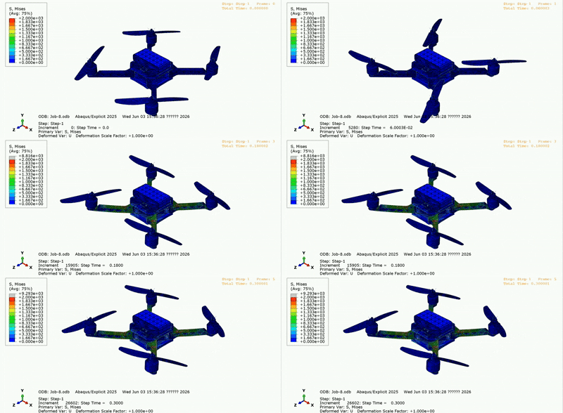
Overview
How does a lightweight quadcopter frame respond as its motors generate lift? In this team project, we built an Abaqus finite element model to examine the load transfer from the motors to the central body during takeoff. The study connects geometry simplification, material assignment, assembly constraints, meshing, and dynamic analysis to the interpretation of stress and displacement fields.
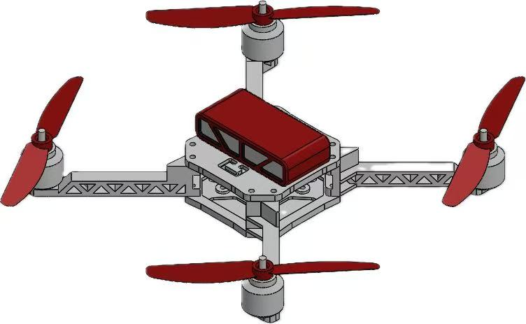
From geometry to a finite element model
- Geometry and materials. We simplified nonstructural details while retaining the frame, arm junctions, and motor supports. The model used carbon-fiber, PA66, and steel material assignments, with equivalent masses representing the battery and electronics.
- Connections and propellers. Tie constraints approximated bolted connections. Motor-axis reference points and kinematic couplings provided a consistent way to apply loads, while rigid-body idealizations simplified the thin propellers.
- Mesh. Modified quadratic tetrahedral elements (C3D10M) accommodated the irregular ribs and arm geometry, which made structured hexahedral meshing difficult.
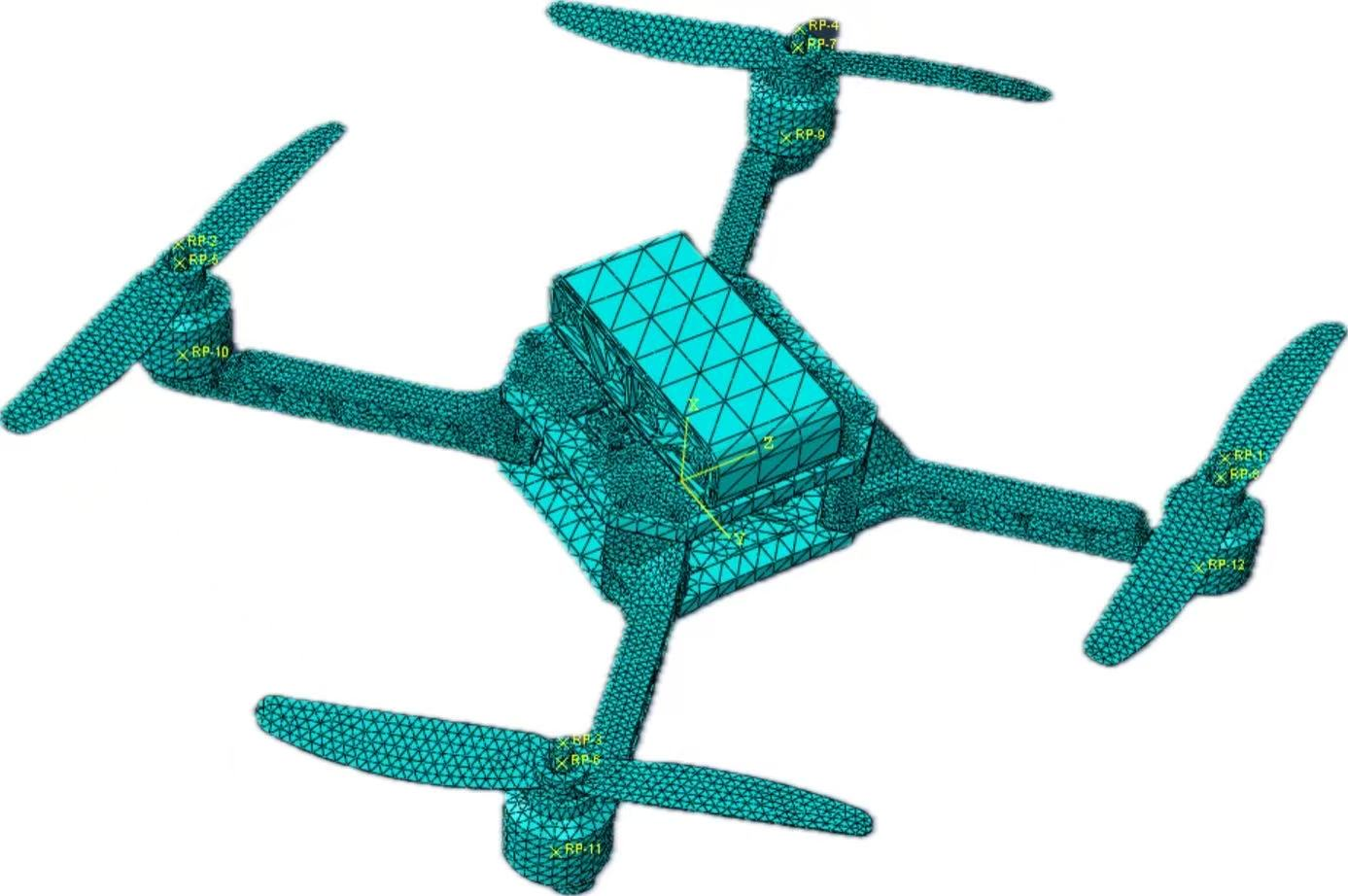
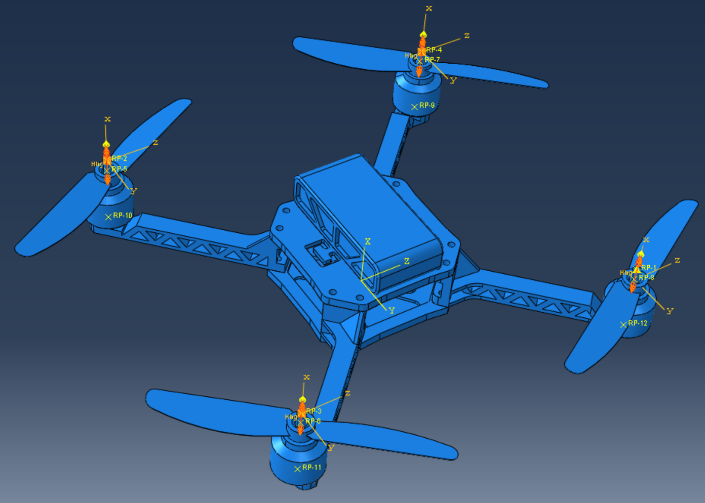
Takeoff loading and solver setup
Gravity acts on the assembly while upward thrust is prescribed at the motor reference points. An amplitude function introduces the loads gradually, and connector velocities represent motor rotation. Aerodynamic effects are represented by equivalent thrust loads.
The Abaqus setup uses Dynamic, Explicit, a 1.2 s analysis period, and geometric nonlinearity. Mass scaling is applied to the whole model at the beginning of the step with a target time increment of 1 × 10⁻⁵ s.
Stress and displacement
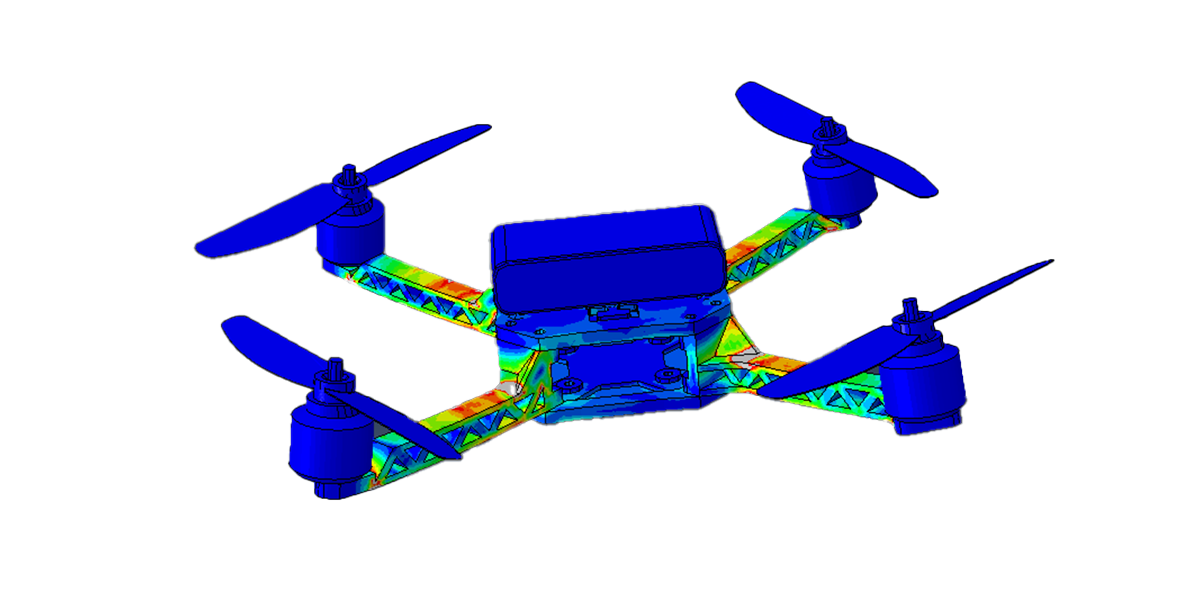
The stress contours highlight the arm-to-body junctions and rib transitions as regions of interest. These locations transfer the motor loads into the central frame and are candidates for local mesh refinement and structural reinforcement.
The displacement output complements the stress view by showing the assembly’s motion during takeoff. The figure below displays the U2 displacement component, rather than displacement magnitude. Because the vehicle is moving, this field includes overall motion and should not be read as elastic arm deflection alone.
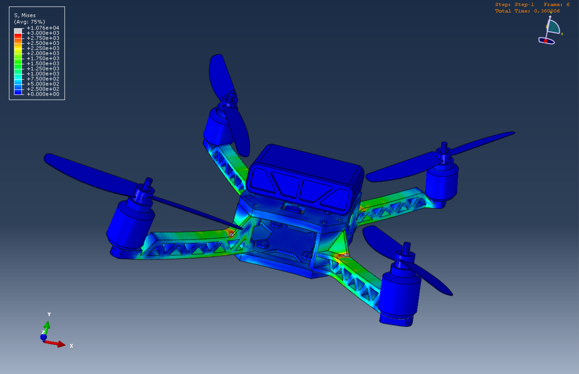
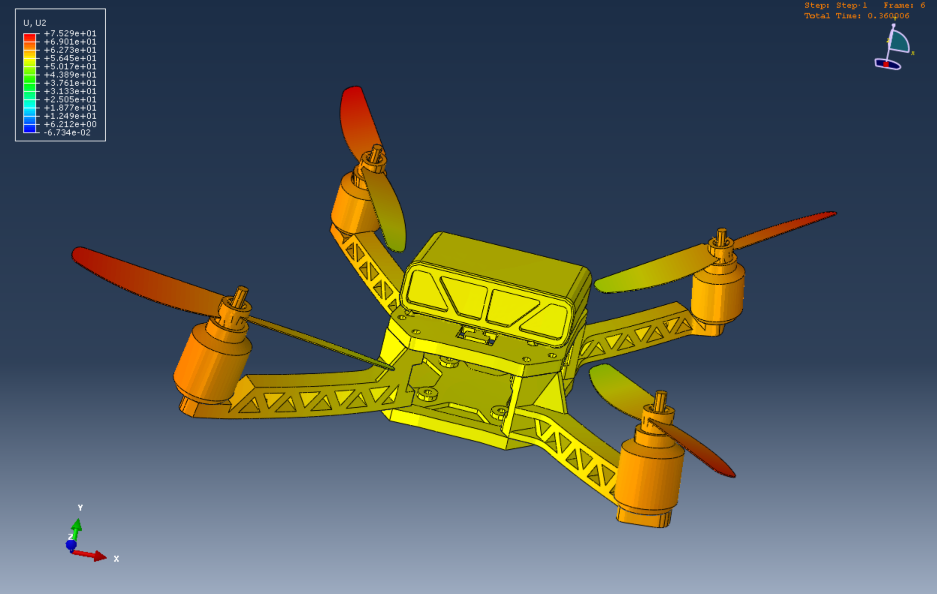
Click any static image to inspect the full-resolution figure and its original legend.
Takeaways and next steps
The project demonstrates a complete structural simulation workflow and identifies the arm junctions as a useful focus for further design work. The next steps are a mesh-convergence study around these junctions, a check of the influence of mass scaling, and material-specific strength assessment. These checks would be needed before drawing quantitative conclusions about safety margins or fatigue life.